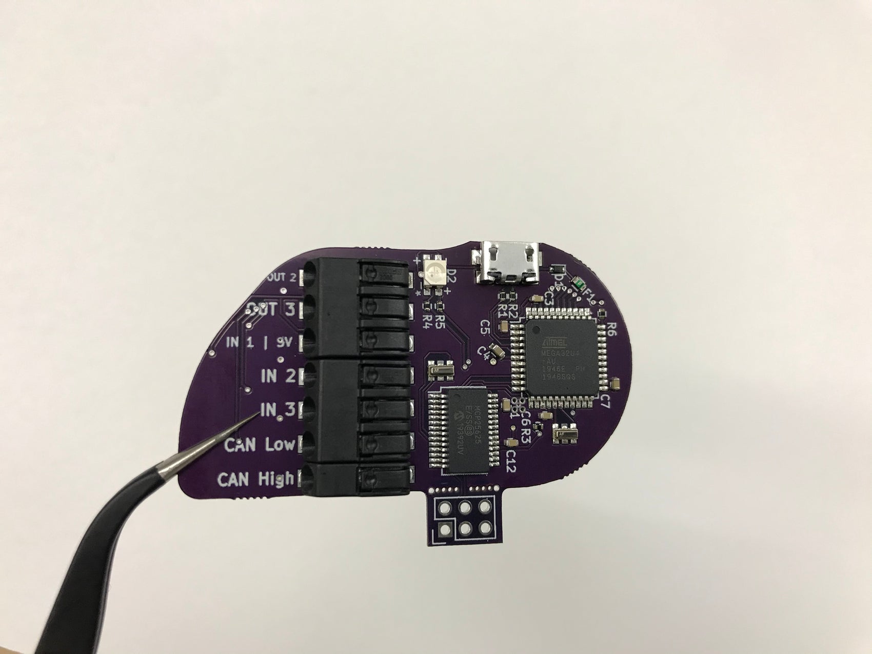
Background: Our previous post (here) analyzed the 5V sensor supply circuit and why some analog inputs deviated from their expected input values. When it comes down to it, any resistive circuit component will 'consume' voltage, and if your analog input is used to measure voltage, from a sensor or switch, then any 'lost voltage' will decrease the accuracy of your analog input.
The current analog input circuit looks like this:

The resistor (R8) is used to prevent too much current from ruining the microcontroller in the Control Module. As a side effect, it does so by eating a little voltage. In the image above, if the input was at 3.2V, the resistor may drop it down a small bit, 0.1V, making the microcontroller read the signal at 3.1V. This difference may not seem significant in this example, but to some it is important and for that reason, we have decided to revamp the analog input circuit as well.
It is important to note that the 0.1V voltage drop across the R8 resistor will change as the current through it changes depending on the device attached to the input. For example, some sensors may only drop the signal 0.1V, while others drop it 0.3V, while other items do not drop any significant voltage at all through the resistor.
That all being said, our planned future improvements include an updated analog input circuit that increases accuracy and signal integrity.
If you have any suggestions, comments, or overall feedback towards typical applications for the Kaizen Relay Control Module, let us know either here in the Blog's comments or via email at Programs@KaizenSpeed.com

